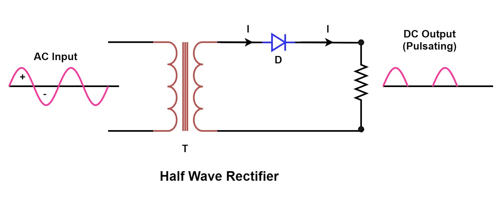
Half Wave Rectifier Circuit Diagram
What are half-wave rectifiers? definition, circuit and working of half Wave half circuit rectifier diagram rectifiers working represents below figure Half wave rectifier
Single Phase Half Wave Rectifier- Circuit Diagram,Theory & Applications
Rectifier wave half full circuit diode voltage diagram output waveform ac figure input positive cycle dc principle working converts Rectifier halfwave difference byjus formula Wave rectifier half circuit diagram hwr
Rectifier circuit input waveform
Rectifier circuit half wave diagram fast build forget don if clickBuild a fast half-wave rectifier circuit diagram Wave half rectifier diode ac voltage supply output circuit peak inverse dc piv operation value load average input when resistanceRectifier capacitor diode circuits load rl circuitstoday 2009.
☑ filter capacitor formula for half wave rectifierRectifier circuit diagram Half and full wave rectifier working principleRectifier circuit principle ac.

Half wave rectifier
Half wave & full wave rectifierHalf wave rectifier – definition, working, circuit diagram, theory Single phase half wave rectifier- circuit diagram,theory & applications.
.


Single Phase Half Wave Rectifier- Circuit Diagram,Theory & Applications

Half and Full Wave Rectifier Working Principle | Circuit Diagram

half wave rectifier | ECE Tutorials

☑ Filter Capacitor Formula For Half Wave Rectifier

Rectifier Circuit Diagram | Half Wave, Full Wave, Bridge - ETechnoG

Half Wave & Full Wave Rectifier | Working Principle | Circuit Diagram

What are Half-Wave Rectifiers? Definition, Circuit and Working of Half

Half Wave Rectifier - Definition, Working, Formula, Applications